* On your first PCB Assembly order!
* Up to $300 discount
 C - A L L E Y
Home | Events | PCB | About Us | News | Contact Us
In this research, we summarize four main aspects of interference in high-frequency PCBs: power supply noise, transmission line interference, coupling, and electromagnetic interference (EMI). We analyze various interference issues associated with high-frequency PCBs and propose effective solutions based on practical experience.
1. Power Supply Noise
In high-frequency circuits, power supply noise significantly impacts high-frequency signals. Therefore, the primary requirement is to ensure that the power supply operates with low noise. It is important to note that the power supply has inherent impedance, which is distributed throughout the system; consequently, noise will superimpose on the power supply. To mitigate this effect, we should aim to reduce the impedance of the power supply as much as possible. Ideally, dedicated power and ground layers should be implemented. Designing the power supply as a dedicated layer is generally more effective than using a bus configuration, as this approach enables the current loop to take the path of least impedance. Additionally, the power layer should provide a dedicated signal loop for all generated and received signals on the PCB. Minimizing the signal loop is crucial to reducing noise, which is often overlooked by designers working with low-frequency circuits.
Here are several approaches to eliminate power supply noise in PCB design:
- **Manage Through Holes**: Through holes may require etching openings in the power layer, which, if too large, can negatively affect the signal loop. When openings are excessively large, the signal may be forced to reroute, increasing the loop area and, consequently, the noise. Moreover, if signal lines are concentrated near these openings and share the same loop, common impedance may lead to crosstalk.
- **Provide Adequate Grounding**: Each signal needs its own dedicated signal loop, with a minimal loop area. This means that the signal and its corresponding loop should be aligned in parallel.
- **Separate Analog and Digital Power Supplies**: High-frequency devices are typically very sensitive to digital noise, so it is essential to keep the analog and digital power supplies separate. They can be connected at the input of the power supply, and if signals must cross from the analog to the digital parts, a loop can be placed at the crossing point to minimize the loop area.
- **Avoid Overlapping Power Supplies Across Different Layers**: If separate power supplies overlap, circuit noise can easily couple through parasitic capacitance.
- **Isolate Sensitive Components**: Components such as Phase-Locked Loops (PLLs) should be isolated to reduce interference.
- **Strategically Place Power Lines**: To further reduce signal loops, power lines should be positioned alongside signal lines to help mitigate noise.

High Frequency PCB Interference Problems And Solutions
2. Transmission Line
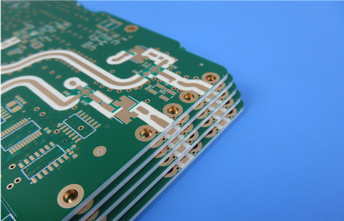
In PCBs, there are two types of transmission lines: strip lines and microwave lines. The primary issue with transmission lines is reflection, which can create numerous problems. Reflection leads to the load signal becoming a combination of the original signal and the echo signal, complicating signal analysis. Additionally, reflection results in return loss, which can have a serious impact on signal integrity, similar to additive noise interference.
1. Reflected signals return to the signal source, increasing system noise and making it more challenging for the receiver to differentiate between noise and the actual signal.
2. Any reflected signal generally diminishes signal quality, altering the shape of the input signal. The main solution to this issue is impedance matching; for instance, the interconnecting impedance should closely match the system impedance. However, accurately calculating impedance can sometimes be complicated, and it may be helpful to use transmission line impedance calculation software.
To mitigate transmission line interference in PCB design, consider the following methods:
a. **Avoid Impedance Discontinuities:** Points of impedance discontinuity occur where the transmission line changes, such as at sharp corners or holes. These should be minimized whenever possible. Recommended practices include avoiding straight corners; instead, use 45-degree angles or arcs. Also, minimize the use of through-holes since each through-hole introduces an impedance discontinuity. Additionally, avoid routing outer signals through inner layers and vice versa.
b. **Avoid Stacked Lines:** Stacked lines are a source of noise. If it is necessary to use short stacked lines, they should be terminated at the end of the transmission line. However, for longer stacked lines, they can reflect as noise when used as the primary transmission line, complicating the situation. Therefore, it is advisable to avoid using stacked lines altogether.
3. Coupling
**Public Impedance Coupling:** This is a common coupling channel where both the interference source and the affected device share certain conductors, such as loop power supplies, buses, or common grounding.
**Common Mode Coupling:** The field common mode coupling will cause the radiation source to cause common mode voltage in the loop formed by the disturbed circuit and the common reference plane. If the magnetic field is dominant, the value of the common-mode voltage generated in the series ground loop is Vcm=- (△B/△t) * area (△B= change in magnetic induction intensity in the formula) If it is an electromagnetic field, when its electric field value is known, its induced voltage: Vcm= (L*h*F*E) /48, the formula applies to L (m) =150MHz below, beyond this limit, the calculation of the maximum induced voltage can be simplified as: Vcm=2*h*E.
**Differential Mode Field Coupling:** This refers to the direct radiation that is received by a wire pair or lead on a circuit board, along with its loop induction. To reduce this type of coupling, wires should be placed as close together as possible. Twisting the wires can further minimize interference.
**Line Coupling (Crosstalk):** This occurs when any line behaves like a parallel circuit due to undesirable coupling, which can significantly degrade system performance. Crosstalk can be divided into two types: capacitive and inductive. Capacitive crosstalk arises from parasitic capacitance between lines, where noise on the noise source is coupled to the receiving line through current injection. Inductive crosstalk, on the other hand, can be viewed as signal coupling between the first stages of an unwanted parasitic transformer. The magnitude of inductive crosstalk depends on the proximity of the two loops, the size of the loop area, and the impedance of the affected load.
**Power Line Coupling:** This type refers to either AC or DC power lines subjected to electromagnetic interference that is then transmitted to other devices via the power line.
Why Choose China PCBA Supplier KSPCBA as Your High Frequency PCB Interference Problems And Solutions Manufacturer?
– Experienced and skilled team
– State-of-the-art equipment
– Strict quality control
– Excellent customer service
– Competitive price

Please send Email to kspcba@c-alley.com or call us through +86 13828766801 Or submit your inquiry by online form. Please fill out below form and attach your manufacturing files( PCB Gerber files and BOM List) if need quotation. We will contact you shortly.
 +86 13828766801
 kspcba@c-alley.com
 https://www.kingshengpcba.com/
 2/F, Building 6, Tangtou 3rd Industrial Zone, Tangtou Community, Shiyan Town, Baoan District, Shenzhen, China, 518108