* On your first PCB Assembly order!
* Up to $300 discount
 C - A L L E Y
 Home | Events | PCB | About Us | News | Contact Us
In the field of electronics, we sometimes see technologies that have roots in the past. Rigid-flex PCB technology originated around 50 years ago and was initially developed to replace wiring harnesses in spacecraft. The first commercial mobile computer, which weighed over 25 pounds, used rigid-flex technology.
Today, rigid-flex PCBs are essential in various applications, including laptops, wearable technology, medical devices, test equipment, and satellites.
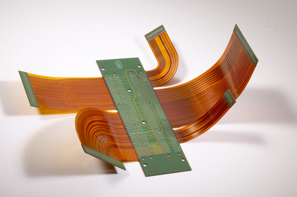
**What is a Rigid-Flex PCB? **
A rigid-flex PCB combines flexible circuit substrates with rigid circuit substrates that are laminated together. Rigid-flex PCBs bridge the gap between traditional rigid PCBs and the unique properties of flexible circuits, which are lithographically etched onto flexible insulating films using highly ductile electrodeposited or roll-annealed copper conductors.
Flexible circuits typically consist of laminates made from flexible polyimides such as Kapton or Norton. These materials are bonded together using heat, acrylic adhesive, and pressure.
Similar to traditional PCBs, components can be mounted on both sides of a rigid board. Rigid-flex designs do not require connectors or connecting cables between sections, as the integration occurs directly between the rigid and flexible circuits. Instead, flex circuits provide the necessary electrical connections.
Each rigid-flex PCB is divided into regions with varying materials and layer counts. Rigid areas may have more layers than flexible areas, and the material transitions from FR-4 to polyimide at the junctions.
Complex designs often transition from rigid to flexible and back to rigid multiple times. At these junctions, it is critical to keep holes away from the transition zone to maintain structural integrity. Additionally, many rigid-flex designs incorporate stainless steel or aluminum reinforcements to enhance support for connectors and components.
The advantages and usage rules of rigid-flex PCB
When designing a rigid-flex PCB, it is important to consider the electromechanical factors that affect both flexible circuits and rigid boards. Pay close attention to the ratio of bend radius to thickness in your design. For flexible circuits, tight bends or increased thickness in the flex area can elevate the risk of failure. Manufacturers recommend maintaining a bend radius that is at least ten times the thickness of the flexible circuit material. Additionally, creating a "paper doll" model of the circuit can help you visualize where the bends will occur.
Avoid stretching the flex circuit along the outer bend or compressing it along the inner bend. Exceeding a bend angle of 90° can lead to increased tension at one point and compression at another on the flex circuit.
Another crucial consideration for ensuring the reliability of rigid-flex designs is the thickness and type of conductors in the flex region. You can reduce mechanical stress and thickness by minimizing the plating on the conductors and opting for pad-only plating. Using thick copper, gold, or nickel plating can compromise flexibility in bends and increase the likelihood of mechanical stress and fractures.
New PCB design tools allow your design team to manage multi-layer stacks, visualize 3D electromechanical designs, check design rules, and simulate the operation of flex circuits. Despite the availability of these tools, the successful design of rigid-flex PCBs relies on effective collaboration between your team and the manufacturer.
Why Choose China PCBA Supplier KSPCBA as Your Rigid-Flex PCB Manufacturer?
– Experienced and skilled team
– State-of-the-art equipment
– Strict quality control
– Excellent customer service
– Competitive price
Please send Email to kspcba@c-alley.com or call us through +86 13828766801 Or submit your inquiry by online form. Please fill out below form and attach your manufacturing files( PCB Gerber files and BOM List) if need quotation. We will contact you shortly.
 +86 13828766801
 kspcba@c-alley.com
 https://www.kingshengpcba.com/
 2/F, Building 6, Tangtou 3rd Industrial Zone, Tangtou Community, Shiyan Town, Baoan District, Shenzhen, China, 518108
We would also like to thank our customers for their trust and support. The company's outstanding achievements are mainly due to the loyalty of our customers, which also encourages and spurs our company to forge ahead.