* On your first PCB Assembly order!
* Up to $300 discount
 C - A L L E Y
About Us | Events | Company Structure | Management Staff Structure | Market Focus | Company Certification | Our Services
When we last left our heroes, we had narrowed down the application and the goal of our quest to quickly design a power supply using free online design tools. We had also set the stage for this series of blogs where we take a look into the various offerings of power supply design software tools.
Our design consists of a circuit that will drive LEDs from a universal AC input. In other words, plug it into the wall and you get light. Although it sounds basic, there are a lot of complications that can arise especially when dealing with UL as well as other safety standards. Throw in the fact that power factor correction is needed and a project could be extended by months. The chosen online design tools help to alleviate this delay by performing many of the project tasks from creating and analyzing the design right down to designing the magnetics and generating a parts list.
Power supplies are particularly hard to simulate due to the large signal nonlinearities and approximations that models make. There have been impressive gains made in this area as software matures and computers get faster at parsing waveforms into finer granularity. However nothing provides insight into the design like the evaluation of the hardware. It’s always best to prove out your design with hardware testing over worst case conditions. That being said, it’s amazing to see how far simulation packages have progressed. In this particular blog, we will go into some of the results you can obtain in an effort to save time while producing a production ready product.
The flyback supply is very popular for low power, offline applications as it combines the transformer and inductor into a single component. In the same manner that it simplifies the components, the design is more complicated than a buck, forward, or boost topology. This is mainly due to the fact that the flyback is based on energy transfer rather than voltage gain. In order to design a flyback a number of equations and load reflection calculations must be used. Fortunately, the simulation packages have the math well programmed. All you have to do is provide values on input voltage and loading while the crunches the numbers and creates the design.
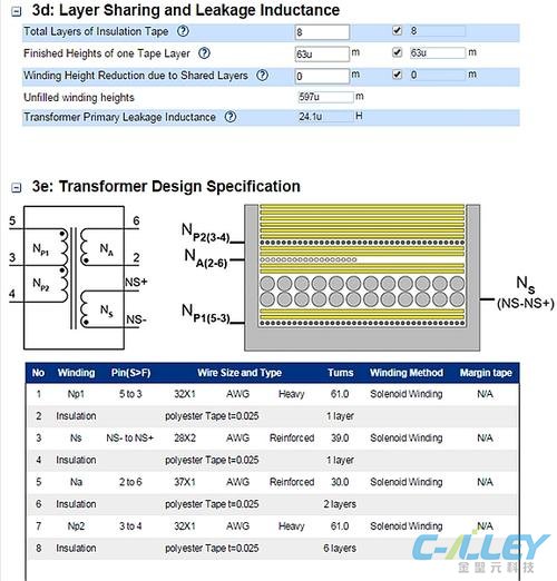
Inductors are often custom designs as well. The physical nature of the coupled inductor is also a concern. For offline application, this includes creepage and clearance safety distances between the primary and secondary windings in order to ensure the proper isolation for safety. Not only are windings physically arranged for safety, proper operation and minimization of parasitics also play a role in the construction. Today’s software tools account for these requirements while providing solutions that save time and frustration. As the figures show, both tools provide illustrations of the inductor design. I liked the detail right down to the winding stack up diagrams. These results can take hours to perform when starting from simple windings and cores.
Power supply design is typically about creating a regulated output. LED drivers are somewhat different as they produce a constant current while the LEDs tend to clamp the output voltage. LEDs operate best at this defined current for ensuring brightness and long life. In order to dim the LED, the current is pulse width modulated or PWM for short. The point is that we now have the two essential black box requirements of our design, the input voltage from a universal AC line and the output current. These parameters are the starting points for initiating the design. For each of the software packages we have chosen, PowerEsim and Fairchild, we will choose 8 LEDs in series with a required current of 350 mA. Right away there are noticeable differences in the tool software tools as the Fairchild design estimates 86% while the PowerEsim estimates 80% (both at low line). Although efficiency is of importance, we are really looking at the completeness of the tool as far as the design goes rather than comparing overall performance. In the initial blog, we chose to look at a number of design components. Here is a sampling of how they worked out.
1) Loss, as in power loss. Each tool produced a power loss value for the overall design as well as for the individual components. The Fairchild software gave nice pie charts so you could determine the major power loss areas. This is essential for proper layout and understanding thermal allocation of copper in terms of pad size.
2) Thermal, Each of the tools provided the temperature rise for every component. The PowerEsim also lists a rating of Pass or Fail which may alert you to potential problems.
3) Dvt report, PowerEsim gives a peak voltage and current report whereas Fairchild lets you set your deratings in the design steps and then provides the stress results.
4) Life and MTBF, PowerEsim allows you to view the estimated lifetime and Mean Time Between Failure (MTBF) for each component.
5) Loop and Stability, PowerEsim provided a cross over frequency and phase margin.
6) Harmonic, PowerESim provided current harmonics. Fairchild provided EMI information and plots as well as power factor.
7) Monte Carlo, PowerEsim lets you choose components to vary in your simulation. This allows you to home in on worst case design operation while focusing on the critical components.
8) Waveform, The Fairchild waveforms from the transient analysis were detailed and rigorous showing the spiking from the parasitics. PowerESim shows steady state waves over a few cycles.
9) Magnetic Builder, Each of the tools provided a magnetics design complete with winding diagram. Fairchild even provided the estimated leakage inductance.
10) BOM and Vendors, These tools provide detailed parts lists of the design. Part numbers and parameter values are listed along with vendor sources.
11) Comp Builder, PowerESim allows you to recommend additional components for their design.
12) Report Builder. Both tools provide you with an opportunity to summarize the overall design. Fairchild does it on one page while PowerEsim provides individual Excel versions for the bulletized parameters in this list.
The first impression of my findings is that I saw thirty years of experience and two years of graduate school flash before my eyes. Whereas I had spent years learning the ins and outs of power supply design, here it was being performed by a machine. I never envisioned I’d be replaced by a robot like countless assembly line workers. Still, there needs to be real world thought processes incorporated into the final design. Layout and spacing issues are major factors when designing a power supply. Custom power beyond these canned designs will always require engineering guidance. I remain impressed that software can produce designs to this level of detail while still having confidence that the multi-output or specialized power designs will require human creation. These more exotic designs will benefit from simulation software which I will address in future blogs as we go beyond readymade solutions into analyzing various systems.
These sophisticated tools get you well on the way to final production. They are an excellent way to save time and frustration so that you can order hardware almost immediately having achieved some level of assurance from simulation results. I like them because I don’t have to sit down and recreate all of my design equations from scratch. I can plug in parameters and have results within a few minutes. The results are realistic and detailed enough to get a good foothold without having to put forth a lot of effort. For those with short design cycles, power supply design software tools provide a wealth of benefits.

Fairchild Coupled Inductor Design Illustration

PowerEsim Transformer Design Illustration

Please send Email to kspcba@c-alley.com or call us through +86 13828766801 Or submit your inquiry by online form. Please fill out below form and attach your manufacturing files( PCB Gerber files and BOM List) if need quotation. We will contact you shortly.
 +86 13828766801
 kspcba@c-alley.com
 https://www.kingshengpcba.com/
 2/F, Building 6, Tangtou 3rd Industrial Zone, Tangtou Community, Shiyan Town, Baoan District, Shenzhen, China, 518108