* On your first PCB Assembly order!
* Up to $300 discount
 C - A L L E Y
About Us | Events | Company Structure | Management Staff Structure | Market Focus | Company Certification | Our Services
In addition to manual inspection to be sure the SERDES bus traces on a routed printed circuit board are error free, use of an automated design rule checker makes such tasks easier.
Despite running at much faster speeds than parallel interfaces, SERDES buses tend to be much easier to implement, as there is a specific set of problems to overcome. As long as the high-level architecture of the SERDES interface is sound, a successful implementation of a SERDES bus boils down to “implementation details.” Such details must usually be verified by manual inspection of the routed board, but an automated inspection methodology, like that facilitated through the use of design rule checking (DRC), can make the task of reviewing SERDES buses much easier. Here are examples where DRC can be useful:
Targeting differential impedance
SERDES buses are routed with differential traces, which need to be targeted at a specific differential impedance. The target impedance is usually 100 ohms differential, but values of 85 and 90 ohms differential are also quite common. This differential impedance must be maintained along the route to minimize reflections and maximize the opening in the eye diagram at the receiver. Impedance discontinuities can come in the form of vias (more on that later), neckdowns in the chip breakout regions, tuning loops to maintain length matching, or any place where the target trace width and/or spacing is changed.

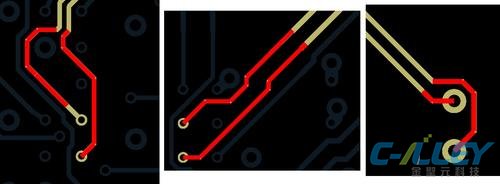
Impedance discontinuities such as neckdowns in chip breakout regions and tuning loops can occur any place where the target trace width and/or spacing is changed.
Like other rules, a differential impedance DRC needs a number of parameters to allow the rule to be tuned for a specific design. These include a target impedance and tolerance, as well as a minimum length for a violation. Setting a minimum length allows the DRC to ignore impedance discontinuities that are “electrically short” and insignificant to the signals. The default value for this minimum length parameter is 50 mils &mash; which equates to around 8ps flight time on a PCB, roughly 1/6th of a 50ps edge. This allows DRC to ignore marginal non-idealities in the routing, and only report significant impedance discontinuities.
These are different via/pin breakouts that were poorly routed, resulting in a differential impedance violation. Often times, the area beneath an IC will become an “exception area” in the layout, so breakouts like these can frequently occur. Some short discontinuities at a breakout are common and usually acceptable, but the impedance DRC was able to catch these, which were particularly bad. In this case, all of these breakouts can easily be re-routed to meet the impedance target.
In this situation a poor breakout also contributed to a length mismatch, which was made up elsewhere along the route of the trace through a tuning “loop”. In this case, both of these impedance discontinuities can be eliminated from the route. The other long impedance discontinuity along this route shows an example where something might not be immediately obvious upon visual inspection, but was caught by the differential impedance DRC. The use of automation allows for finding such hard-to-see problems with the board, which may be the result of a slightly different spacing or even a slightly different trace width.
Watching out for via discontinuities
The most significant impedance discontinuities on a SERDES channels are usually the vias, especially vias with stubs. A Via Stub DRC, which looks for vias with stubs greater than a certain threshold, can be used to identify problem vias. A Via Stub DRC can search the entire board in seconds and find all the vias which have stubs. These can then be minimized or eliminated by changing the layer span for the signals, using blind or buried vias, or back drilling.
Another issue common with vias is the lack of proper stitching vias. Stitching vias are absolutely crucial for fast, single-ended signals, but are also important for SERDES signals to minimize the potential of common-mode radiation. A vertical reference plane change DRC finds signal vias that lack nearby stitching vias (or stitching capacitors, depending on the layer span).

Please send Email to kspcba@c-alley.com or call us through +86 13828766801 Or submit your inquiry by online form. Please fill out below form and attach your manufacturing files( PCB Gerber files and BOM List) if need quotation. We will contact you shortly.
 +86 13828766801
 kspcba@c-alley.com
 https://www.kingshengpcba.com/
 2/F, Building 6, Tangtou 3rd Industrial Zone, Tangtou Community, Shiyan Town, Baoan District, Shenzhen, China, 518108